Simple HDMI Frame Buffer
Introduction
A few FPGA development boards now have HDMI outputs, and it's quite easy to use these to display an image. Here's one way you could display a static image on a Digilent Atlys!
This design is based on XAPP495, but you may want to use my 'fixed' version, which works on ISE 14.
The vtc_demo basically has two parts:
- An HDMI transmitter (dvi_encoder.v)
- An image generator (hdclrbar.v)
We will assume that the HDMI transmitter logic already does everything we want and I have not modified it any further (other than fixing the clock generation).
The image generator only displays coloured bars, which are not very interesting! We will replace it with a new module called image_gen, which displays an image stored in the FPGA’s Block RAM.
Verilog module setup
 module image_gen(
   input            i_clk_74M, //74.25 MHZ pixel clock
   input            i_rst,   // not used
   input            baronly, // not used
   input [1:0]      i_format, // not used
   input [11:0]     i_vcnt, //vertical counter from video timing generator
   input [11:0]     i_hcnt, //horizontal counter from video timing generator

   output [7:0]  o_r,
   output [7:0]  o_g,
   output [7:0]  o_b
 );
If you examine how hdclrbar works, it really just has two inputs, the (x, y) coordinates that dvi_encoder wants to draw to the screen next. These signals are called i_hcnt and i_vcnt. The dvi_encoder supplies these coordinates and expects an RGB pixel value one clock cycle later at o_r / o_g / o_b. For this exercise we'll emulate the hdclrbar interface exactly to make it easier to change from one to the other - it also includes some other input signals that we will not use and just leave unconnected.
BRAM creation
We will use a BRAM block memory to hold the pixel data for an image. Because the Spartan-6 does not have enough BRAM to fit a high resolution image, I have scaled it down to 256x192 with 6-bit colour depth. The Spartan-6 BRAMs are exactly 18 bits wide. If we use 6 bits for each of red, green and blue this is convenient because it means we can store all colours for a single pixel in one BRAM memory location. This is important because it takes one clock cycle to fetch a single 18-bit word from BRAM. If a pixel was stored in multiple memory locations, we would need multiple clock cycles to retrieve a single pixel.. so the memory would need to be run much faster than dvi_encoder. This is possible, but it would be more complicated to design. Alternatively you could use two BRAMs in parallel to create a 36-bit word.
Anyway, 884736 bits (256x192x18) is well within the Atlys' Spartan-6 LX45 BRAM capacity, so this is a good size to use. It is also exactly one quarter of 1024x768 (a standard screen resolution) so we can make the image nearly fill the screen by making it four times larger in both directions - a very simple operation to do in digital logic.
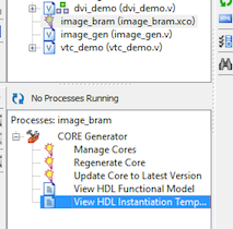
Here's how to create a BRAM using the CORE Generator
- Create a new IP core called image_bram
- Select Block Memory Generator
- Native Interface
- We will use Simple Dual Port RAM: we need one R port (for video transmit) and one W port (for programming a new image in a future exercise) only.
- Leave other options at defaults
- Memory Size:
- Write Depth of 256*192 = 49152
- Write Width = 18
- Read Width = 18
- Enable:
- Port A (write) needs to have "Use ENA pin"
- Port B (read) should always "Always Enabled". We always want to be reading data from the BRAM.
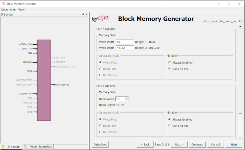
- We will want to use an Init file to store our picture at some stage, but we don't have one yet. Leave all of the other options as defaults.
- Generate the core! This will take a few minutes to complete.
Once created, you can copy the HDL Instantiation Template for the new BRAM and paste it into your image_gen module (or read on to see mine).
Module design
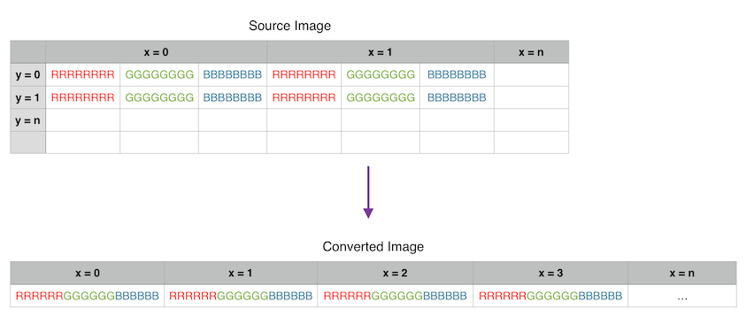
The design for my image_gen module is very simple: it just converts the incoming i_hcnt/i_vcnt values into an address in the BRAM. A BRAM memory is one dimensional: the 256x192 pixels are stored as 49152 consecutive 18-bit values, so we just need to convert the x,y coordinates to a single value using the operation address = (x + y*256) - remember that image is 256 pixels wide. Because the screen resolution might be even larger than this, we need to define some signals that will tell us if the requested pixel location is outside of our stored image.
 wire h_too_big, v_too_big;
 assign h_too_big = i_hcnt[11:10] > 2'b00; // > 1024
 assign v_too_big = i_vcnt[11:8] > 4'b0011; // > 768

 always @*
 begin
   if (h_too_big | v_too_big)
     pixel_address = 16'd0;
   else
     pixel_address = (i_vcnt[9:2] * 256) + i_hcnt[9:2];
   end
If the x,y coordinate is larger than the image (h_too_big | v_too_big), we instruct the BRAM to return the pixel value in memory location zero, which is just the top-left pixel of our image. If we don’t do this, the picture will be repeated horizontally in an unusual way.
If not, we perform the calculation to map the coordinates to the linear memory address. Note that we also shift the incoming coordinates right by two bits, which makes the image four times larger (2^2) in both directions. This means that the 256x192 image is actually displayed on the screen as 1024x768. Each pixel in the source image is displayed as a square of 4x4 pixels on the monitor.
BRAM instantiation
Here is the instantiation of our BRAM. First of all, the BRAM's output enable is always high - we always want it to be returning pixel data.
 wire [17:0] doutb;

 image_bram image_bram (

   // Port B (read)
   .clkb(i_clk_74M), // input clkb
   .addrb(pixel_address), // input [15 : 0] addrb
   .doutb(doutb), // output [17 : 0] doutb

   // Port A (read).
   // None of these signals are used at the moment - in the future they could be used to
   // upload a new image to BRAM without regenerating the bit file.
   .clka(i_clk_74M), // input clka
   .ena(), // input ena
   .wea(), // input [0 : 0] wea
   .addra(), // input [15 : 0] addra
   .dina(), // input [17 : 0] dina
 );
Here the output signals are connected to doutb, which is the BRAM’s data output register (on port B - we are not using port A for anything yet). Because the colour values are 6-bit, convert each of them back to 8-bit by adding two zero bits to the right hand side (the least significant bits). This just means that the image doesn’t have as many colours as the original, but it is not too noticeable because the image is very low resolution and looks terrible anyway!
 assign o_b = {doutb[17:12], 2'b00};
 assign o_g = {doutb[11:6], 2'b00};
 assign o_r = {doutb[5:0], 2'b00};
Creating a .COE file of your image
We have not implemented a way for the FPGA to decode a compressed image format such as JPEG, so we first need to convert an image to the correct size and our uncompressed 'raw' 18-bit colour format. You can write a simple program to do this. Here's an example using Ruby:
 #!/usr/bin/env ruby

 require 'rubygems'
 require 'rmagick'

 img = Magick::Image.read('image.jpg').first
 thumb = img.thumbnail(256, 192)

 puts "memory_initialization_radix=16;"
 puts "memory_initialization_vector="

 0.upto(thumb.rows-1).each do |r|
   scanline = thumb.export_pixels_to_str(0, r, thumb.columns, 1, "RGB");
   i = 0
   while i <= scanline.length-2 do
     puts ((scanline.getbyte(i) >> 2) + ((scanline.getbyte(i+1) >> 2) << 6)  + ((scanline.getbyte(i+2) >> 2) << 12)).to_s(16) + ","
     i = i+3
   end
 end
Here's an example using Matlab (which I have not tested). It is incredibly slow, probably due to my inefficient Matlab coding style.
 im = imread('image.jpg');
 im = uint32(imresize(im, [256 192]));
 im_out = zeros(1, 256*192, 'uint32');

 for J = 1:192,
   J
   for I = 1:256,
     red = bitsrl(im(I, J, 1), 2);
     green = bitsll( bitsrl(im(I, J, 2), 2), 6);
     blue = bitsll( bitsrl(im(I, J, 3), 2), 12);
     im_out( 1 + (I-1) + (J-1)*256) = red+green+blue;
   end
 end

 outfile = fopen('coefile.coe', 'w');
 fprintf(outfile, 'memory_initialization_radix=16;\r\n');
 fprintf(outfile, 'memory_initialization_vector=');
 for I = 1:49152,
   fprintf(outfile, '%x,\r\n', im_out(I));
 end
 fclose(outfile);
Please note that these write the image into BGR format (within the 18-bit BRAM word) rather than RGB. It doesn't really matter which order you use, as long as the output of your BRAM is hooked up to the appropriate signals, unless you want the colours to be swapped.
Re-open the BRAM core you generated and selected the new .coe file, then re-generate the core.
Connecting to vtc_demo.v
In vtc_demo.v you can now replace the hdcolorbar instantiation with image_gen directly. I have just commented the hdcolorbar out so that I can swap back quickly.
   //hdcolorbar clrbar(
   image_gen clrbar(
     .i_clk_74M(pclk),
     .i_rst(reset),
The result
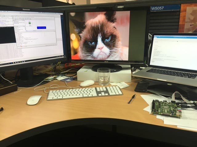
This design currently fails to meet timing constraints for some reason, but it does work!
Where to from here
Here are some suggestions for things you could do using this basic design:
- Add the ability to upload a new image on the fly, perhaps via USB-serial. This would let you change the image without programming a new bit file. This could be done with a UART (e.g. from Picoblaze), a state machine, and the second port of the BRAM we created. It would be nice to be able to upload a raw RGB image and perform the 8-to-6 bit conversion on the fly, or even to decode simple image formats such as Windows BMP
- Create a character generator. Instead of storing complete images in a frame buffer, use a character ROM to store a typeface and a smaller BRAM to store the positions of where characters should appear on the screen.
